Linework and breaklines
The linework comes through the way it was meant — arcs included. That is where a conversion most often fails in practice, and you only see it when the machine digs to it.
- Arcs stay arcs: no more spikes where there was a curve
- Layers and colours are kept, so you can see what is what
- Breaklines are laid on the terrain model instead of cutting through it
- Linework in a separate DXF is matched to the right design automatically
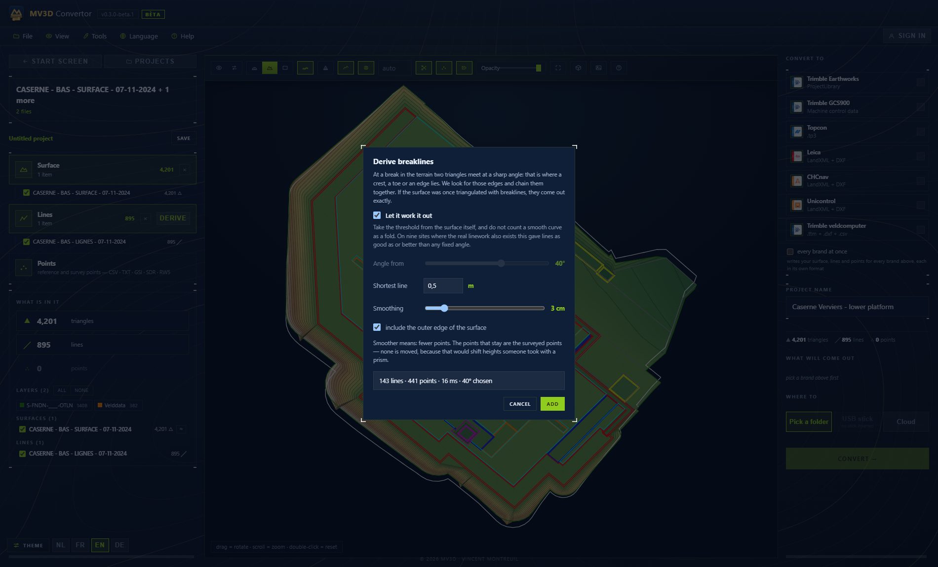
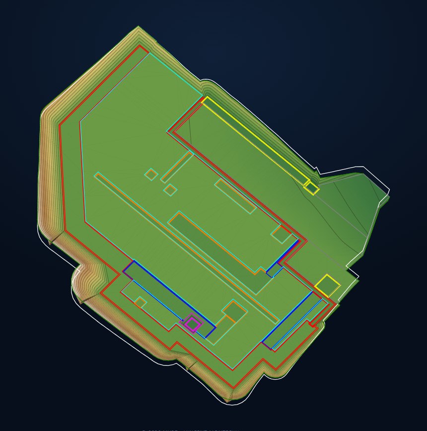
A design is rarely just a surface. Manhole edges, kerbs, slopes and alignments all live in the linework, and the linework is exactly what a conversion treats worst: arcs swinging the wrong way, lines left at elevation zero, layers losing their colour.
We treat that linework as the main thing rather than an afterthought. Arcs are recomputed and put in the right direction of rotation, every line is laid on the surface it belongs to, and if the linework sits in a separate file, the program finds the right one itself.
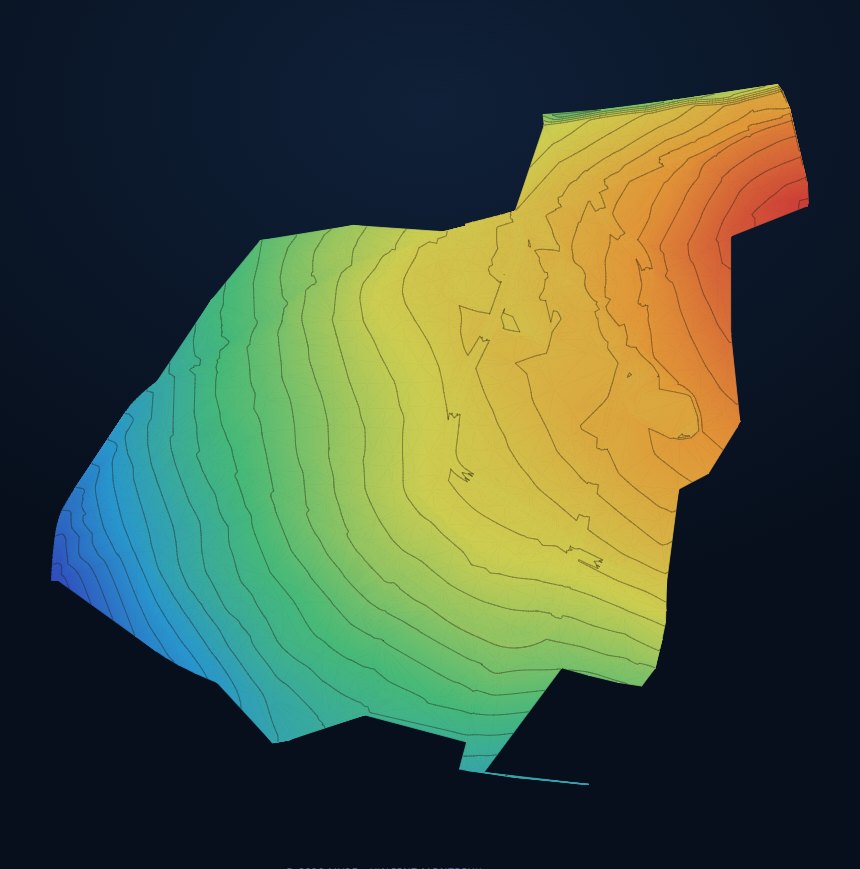
Screens from the program itself — not a redrawn impression.
Reads (import)
Writes (export)
Why arcs go wrong
A DXF describes an arc as a line with a bulge. If a converter picks the wrong direction of rotation, that arc swings the other way — and in a list of coordinates that looks perfectly normal.
Laid on the terrain
Linework from a drawing often sits at elevation zero. We lay every line on the surface it belongs to, with enough intermediate points to follow the ground instead of cutting through it as a straight chord.
The right DXF
If the linework sits in a separate file next to the design, the program finds it: it compares the extent against the surface and weighs name and date, so you get the right version and not the oldest one.
Sees from the colours which line is the kerb and which the slope
Passes on surveyed linework without redrawing it
Digs the pit with the edges shown instead of by feel
You might also like
Conversion
Convert any format to every machine brand, both ways — CAD-independent, no double work.
More →3D viewer
View any machine file or design in 3D right away — orbit, measure and inspect before it goes to site.
More →The right file per brand
Every brand expects its own format. The Converter writes that file and you download it — transferring works the way you are used to.
More →Want to try it yourself?
The MV3D Converter is coming soon. Leave your email.